Gaskets
It is critical that the correct gasket(s) are selected and installed correctly in the application. Failure to do so can lead to lose of containment, potential hazard, and pollution to the environment.
Gaskets assist in creating the integrity between the two flange faces, maintaining the contents of the system and the internal pressure at that joint.
Important - never cut or deform a gasket to fit a flange.
Ring Type Joint Gaskets (RTJ)
These types of gaskets are metal rings that fit between the two machined finished grooves on the RTJ flanges. They are more commonly utilised for high pressure applications.
Flange integrity is achieved and maintained due to the metal-to-metal contact between the gasket and the flanges.
RTJ commonly available:
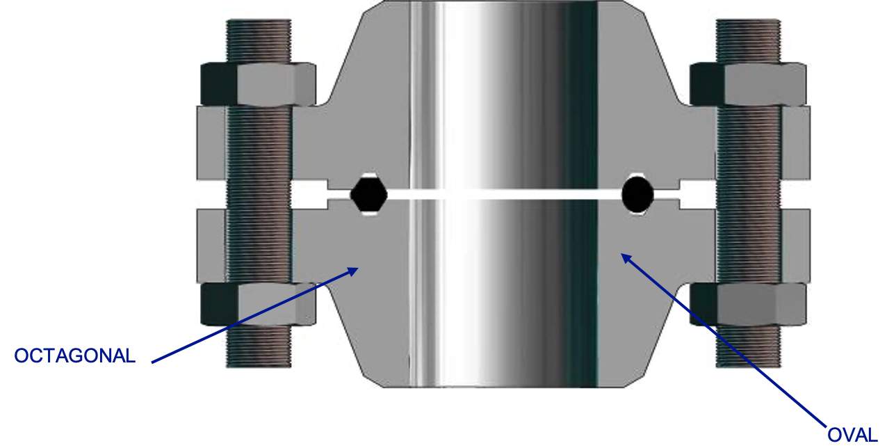
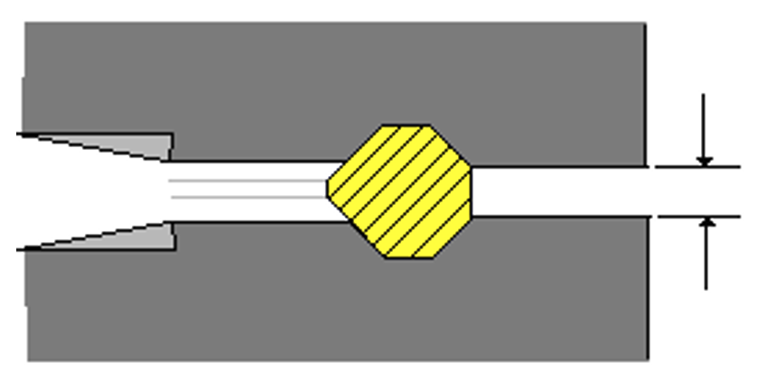
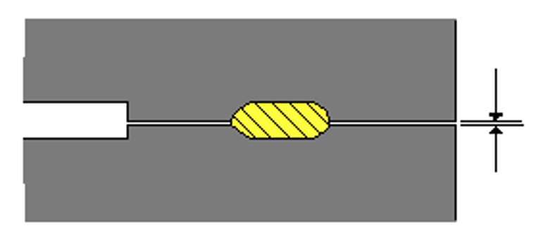
R Type: There are two styles of RTJ either oval or octagonal.
- The first RTJ designed was of the oval style format. The octagonal style RTJ is a later modification to the design providing greater integrity qualities. R type designs are utilised for flange rating class 150 to 2500 flanges. Normally they are not used on flange ratings below class 900. Piping specification states which style of RTJ shall be used.
The gasket plastically deforms through bolt loading R type rings may be used on either flat face or raised face RTJ flanges The machined groove in the flanges should match the RTJ gasket profile.
RX type. The machined groove for an RX type gasket must suit the octagonal style ring and not oval style.
The RX RTJ gasket is wider than the R type gasket and the distance between the joint faces will be greater.

RX gaskets are commonly specified up to class 5000 API 6A Type 6B flanges. They are utilised in situations where a more efficient seal on the joint is needed which is resilient to any possible vibrations that may be seen for example, on Xmas trees and wellheads.
Viewing the cross-section of the gasket shows the asymmetric (non-symmetrical) style self-energising gasket. The bevel shown on the outside of the ring makes the contact initially with the machined finish of the flanges assisting in the preloading of the RTJ gasket against the outer surface of the groove.
BX type: These BX type rings are pressure energised ring type joints.
When fitted in the correct manner, the joint allows for virtual full face contact allowing the gasket to be fully compressed on the inner and outer diameters.
The gasket has a pressure balance hole, allowing for the equalisation of the pressure that may be trapped in the grooves.
BX rings are only required for use on API 6A Type BX flanges and are utilised on joints with a rating from class 5000 to 15000.
BX gaskets, R and RX gaskets are NOT inter-changeable. The machined groove on a flange face accommodating a BX RTJ gasket is different in design from that of R or RX gaskets.
It is essential that the gaskets faces are inspected carefully during the maintenance periods. It is important that the uniform compression is maintained at all times during the tightening process.
RTJ Gasket Identification and Specification
Type of joints: Piping specifications will give specific details to indicate which type of gasket is required.
Ring number: The gaskets are etched stating the size, type and class.
Material: A wide range of gasket materials are available.
For example:-
- Soft Iron: D
- Low carbon Steel: S
- Stainless Steel: S304: S316: S347: S410
Standard: Either ANSI B16.5 or API 6A; these are stated in the piping specifications.
Identification: Etched on the outside edge of the RTJ ring.
Spiral Wound Gaskets
These style of gaskets are available for the full range of pressure classes from 150lb through to 2500lb but they are mainly used on intermediate pressure systems e.g. class 300, 600 and 900 flanges.
Utilised on RF flanges with a machined centre line average (CLA) between 125 -250 micro inches.
The design of these gaskets differs greatly, but the standard style of gasket has an out and inner carrier ring.
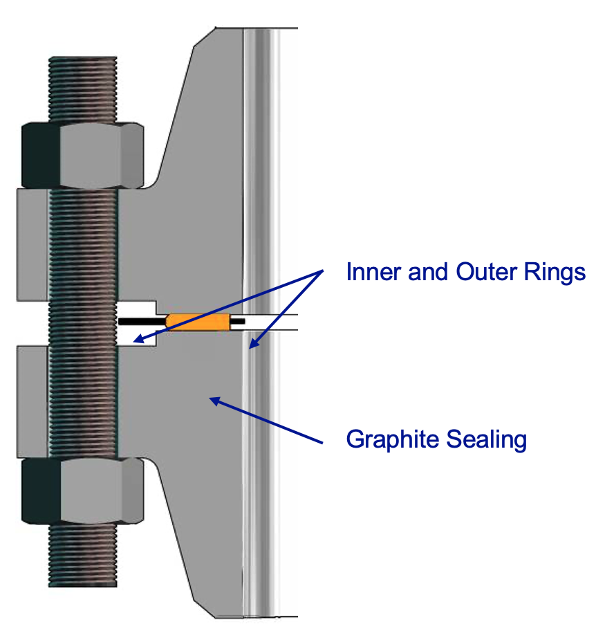
Spiral Wound Gasket with Inner and Outer Rings
Spiral Wound Section
This creates the seal between the two mating faces of the flanges. The gaskets are of a spiral wound design and can have a multitude of different fillings to assist in the sealing operation.
When the load is applied to the gasket by compressing the flanges together, the windings squash and squeeze together, utilising the machined grooves of the mating faces to create a seal.
Inner Metal Ring
The inner ring is designed to stop the windings from being over compressed by providing additional support, a physical stop. It also assists in the prevention of any turbulence that could be produced by the medium passing through the pipework. Any instability created in the pipework can lead to excessive vibration and erosion of the inner walls of the piping system and flange faces leading to possible loss of flange integrity. It is important that we make sure that the gasket is fitted centrally and is the correct gasket for the application.
Outer Metal Ring
The outer ring acts like a compression stop, preventing the flange from being over tightened and damaging the gasket and sealing faces of the flange. Additionally, it acts as an anti-blow out device, physically preventing the gasket from being forced out by the internal pressure of the system. It assists in centring the gasket on the sealing face by positioning it within the bolts holding the flange together.
Gaskets should be checked carefully against the P & ID and the flange stamping.
Filler Material
The piping specifications should state the gasket filling required for the application and these can be supplied by various gasket manufacturers.
In some cases, asbestos filled gaskets could be specified. Note that COSHH regulations cover the use of Asbestos, which can be hazardous to health and even though trapped within the spiral winding. Full risk assessment and procedural documents should be made available and should be consulted.
Other types of filler materials are also used depending upon the nature of the application.
Compressed Sheet Gaskets
PTFE sheet, Compressed Asbestos Fibre (CAF) and Compressed Sheet Gaskets are used normally on low pressure rated systems found on class 150 and 300 flanged joints. Please note that working with asbestos requires an approved technician.
Usually compressed sheet gaskets are utilised on raised face (RF) applications with two common styles. A Full Face where the gasket fits over the bolt holes and a Flat Face where the gasket sits within the bolt holes!
Although the simplistic design of these gaskets makes them easy to utilise we should endeavour to remember that respect should be paid to the installation of the gasket and the condition of the flange faces.
The gaskets are designed to be used on machined finished flanges with a surface CLA finish between 125 micro inch to 500 micro inch. And the material is of a sufficient malleability that when compressed it beds into the grooves of the flange creating a seal.
It is also important that the specification of gasket used on the application is such that materials, size and thickness of the gaskets are correct as they are all crucial to maintaining the integrity of the joint.
Certain types of gasket may be coated with graphite material. The graphite has a non-stick property that enables the removal of the gasket from a flange without or with little residue of the gasket material being left behind.
Graphite coated gaskets SHOULD NOT be utilised for the following instances:
- Austenitic stainless steel flanges on water duties
- Aggressive water duty (e.g. cement lined pipework).
- Duties where temperatures exceed 450 degrees C.
CAF gaskets contain asbestos meaning that additional PPE may be required and risk assessments carried out prior and possibly during the removal and installation of the gaskets. Particular attention should be paid to handling of the gaskets and this kind of job will require approved technicians with specialist training.
When the removal of an old gasket is carried out, damp or wet down the gasket with water to absorb any asbestos dust that may be freed into the atmosphere. All loose CAF waste should be disposed of in the correct manner and clearly identified as “asbestos waste” by an approved technician. Full COSHH procedures are available upon request and shall be strictly followed.
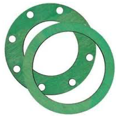
Flat Rubber Gaskets
Commonly flat rubber gaskets are used in the less hazardous and aggressive environments such as low pressure water systems. They are greatly limited in application by their ability to cope with different conditions such as temperature, pressure and chemical resistance. They are also liable to creep. This is when the gaskets may be over tightened or due to repeated usage.
Normally rubber gaskets are used on full face and flat face flange applications.
There are a large range of materials used in the manufacture of these types of gasket, but mainly used is Neoprene. Other possible materials include Natural Rubber, Nitrile and Viton.
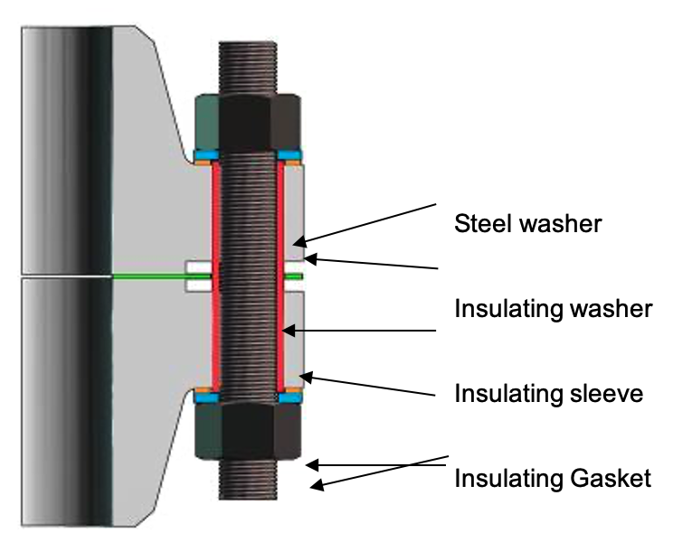
Insulating Kits
These insulating kits are designed to prevent dissimilar metals coming in contact with each other. They electrically insulate the flange components helping in the prevention of galvanic corrosion between flanges that can occur, for example, between carbon steel bolts to a stainless steel flange.
Insulating gaskets are not normally utilised for oil and dry gas duties.
Insulating gaskets are made from different materials and designs, some of the materials are more fragile then others, meaning that the torque figures that are applied to these bolts are lower then we would normally apply to a flange without an insulating gasket set fitted.
If used, the insulating kit will consist of the following:-
- Insulating gasket
- Insulating sleeves to be placed around the studbolts.
- Insulating washers and steel washers.
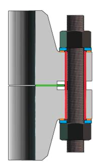
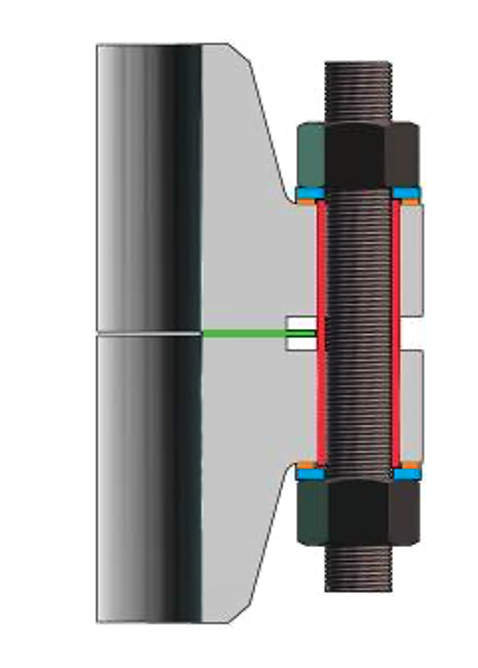
There are three versions of insulating kits available:
Full face gasket insulating set
Suitable for both flat face and raised face Flanges. This type of gasket has the advantage of reducing to a minimum the potential ingress of any foreign matter between the flanges reducing the risk of a conductive path between the two mating faces of the joints.
Inside bolt location gasket insulating set
This set is only suitable for raised face flanges and is located within the bolts.
Ring joint gasket insulating set
The insulating oval RTJ will fit into a standard RTJ flange ring groove. Some sites consider these kits to be unreliable.
Insulating Kit Identification and Specification
Nominal pipe size and pipe schedule: Need to be specified.
Flange pressure class: Always to be specified in the piping specifications.
Style of insulating kit: Full face or inside bolt location.
Gasket material: Usually phenolic laminate or neoprene faced phenolic laminate.
Insulating Kits – Do’s and Don’ts
Do’s
- Use new insulating gasket kits only.
- Good insulation requires the insulating parts of the kit to be clean and in perfect order.
- Always follow manufacturer’s installation instructions provided with the gaskets.
- Use a torque wrench or tensioning equipment to tighten the studbolts or bolts to the manufacturer’s standard recommendations. It is very important that we follow the recommendations as these types of gaskets are susceptible to fracturing or crushing if overloaded.
- Clean the flange face and the studbolts before the installation of the gasket. Inspect for any potential conducting paths between the two mating flanges, these could otherwise reduce the insulating gaskets effectiveness.
- If in doubt, seek advice from your supervisor / engineering.
Don’ts
- Do not re-use old, damaged or unclean insulating kits. These will reduce the effectiveness of the gasket and may lead to integrity failure.
- Do not mix parts from different insulation gasket kits.
- Never use air driven wrenches when tightening flanges, as these can cause the insulating washers to splinter and crack.
Gaskets – Do’s and Don’ts
Do’s
- Always clarify the type, class, size and material specification of the gasket before using it. This can be done by checking with the piping specification to confirm that it is correct.
- Inspect the gasket for any possible damage. Making sure that it is free from any contaminants.
- Fitting the gasket centrally is very important.
- Maintaining uniform flange compression is critical to the reduction in potential flange failure. If an even all-round separation is not maintained, the gasket could be crushed or deformation may occur and integrity could be lost.
Don’ts
- Do not re-use old gaskets unless authorisation in writing has been obtained from the plant engineer. A brand new undamaged gasket should be utilised for all joints being assembled.
- Do not use a gasket that cannot be identified. Different gaskets may seem to fit the application, but this is not a guarantee, always check the piping specifications.
- Do not cut or deform a gasket to fit a flange. Gaskets that do not fit the application are commonly the incorrect ones chosen.